|
Swing Axle (aka S/A)
|
Adjustable spring plates were something that
one of my brothers really wanted, but they
cost way too much for him to buy. Well I wasn't going to buy
him a pair, but I figured that they couldn't be too hard to
make!
I made him a Swing Axle pair, and they worked so well that
I made myself an IRS pair! Here is how I did it. |
IRS
|
| |
|
|
| First of all you have to get hold of two pairs
of spring plates. Which kind you should use depends on what
you want. For the S/A ones I used two sets of S/A spring plates,
because it was going on a stock setup. However from my IRS ones
I used one IRS set, and one S/A set. This is because I wanted
extra tyre clearance on my IRS Baja. Pick the spring plates
that suit your application best. |
|
|
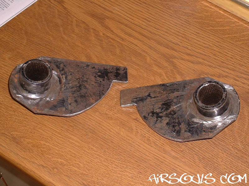
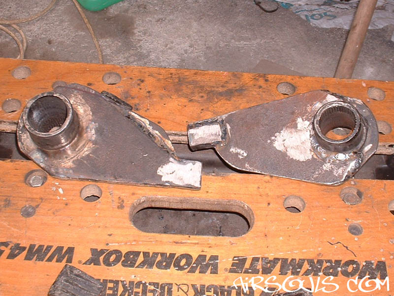
1. Take one pair of spring
plates and cut them down to the shape shown in the photo.
(We shall call the piece A.) Make sure that you make them
as opposites, or one side won't work! After some interesting
maths I worked out that the optimum length of this section
is about 18cm to 18.5cm.
This gives plenty of adjustment. :D (If you are making an
IRS pair, check them for clearance as this bit could foul
the trailing arm.)
IMPORTANT: Don't get lazy and use a straight
edge rather than a curve, it is there for strength. I was
lazy on my IRS ones and they flexed too much. I've now fixed
this by doubling the thickness of this piece. (More details
at the bottom of this page.) |
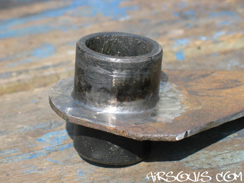
| 2. Next you need to get rid
of the weld on one side of the cut plates (the non-splined
side). You could have it machined down on a lathe, but as
the tube is a constant diameter already I just ground it down
carefully. You should be left with a nice constant diameter
all the way down to the plate itself. I used a cutting disc
on an angle grinder and was happy with the result. |
|
|
3. Now to the other pair of spring
plates. (We shall call the piece B.) On these ones we cut the
tube (that the torsion bars sit in) off completely. Take care
not to damage the plate itself. |
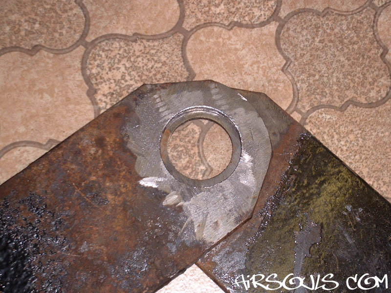
| 4. The next bit is probably the
biggest pain! The hole in the middle has to be opened up enough
to slide over the piece we have already made. (It needs to slide
over the tube that we ground the weld off of in 2.)
I found no way to do this other than with a round file, but
I'm open to suggestions! |
|
|
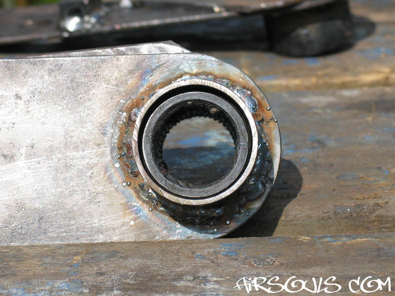
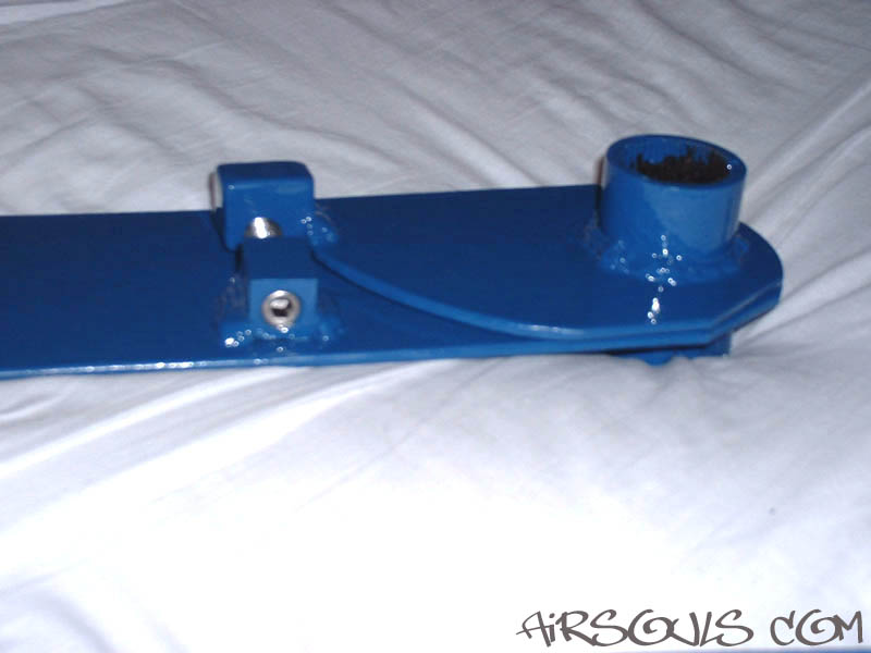
5. Once you have a nice fit over
the tube you need to make a collar to give the plate extra support.
The collar can be a scrap bit of tube (I think that mine came
from a MacPherson strut on a scrap Astra). It should be a good
fit, but not so tight that it's hard to move. When you are happy
with the fit weld the collar on to the spring plate. |
| 6. When the collar is welded
onto the spring plate check pieces A and B for fit again. This
is the point where you can give it a bit more filing so that
it pivots nice and smoothly. |
|
|
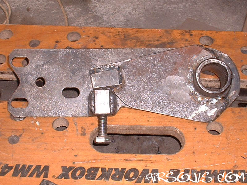
7. Lucky for me I had some
scrap square bar kicking around. I welded it to the spring
plate to make a mounting for the adjusting bolt. This mount
needs to be welded on to the bottom of the spring plate, as
the bolt threads up through the mount to push on piece A.
The mount should also be welded on to the outside of the plate
as shown in the photo. |
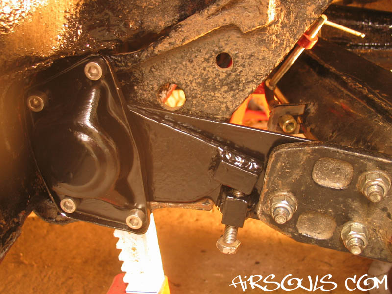
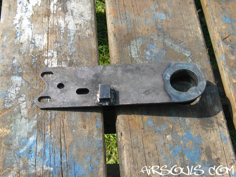
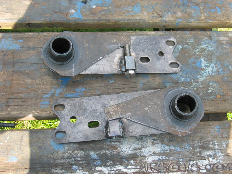
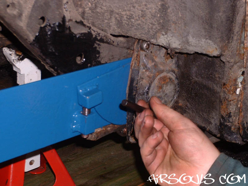
8. In this photo things should
start to make more sense! I had the mount drilled and tapped
at a local engineering firm (but you could do it yourself
with a pillar drill). When the bolt is in place it lines up
with the 'tab' on piece A. Threading the bolt in and out causes
piece B to rotate about piece A. It's as simple as that. :-)
Note: I have used M12 bolts on all the ones
I made. I wouldn't advise using anything smaller. |
|
|
9. To give the bolt a good surface
to press against I welded some of the square bar onto piece
A. Once that is done you're basically finished! |
| |
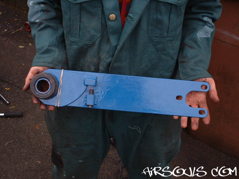
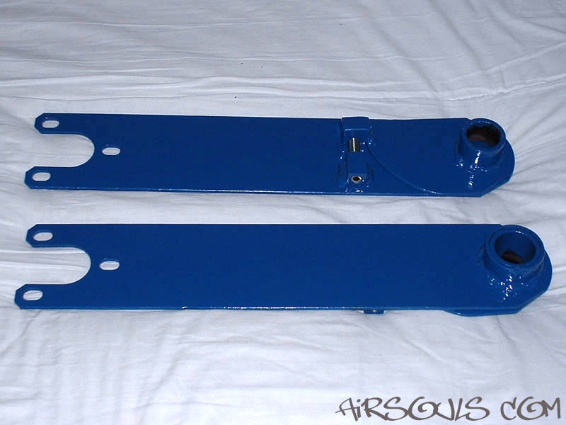
The finished
S/A adjustable spring plates: |
|
|
|
|
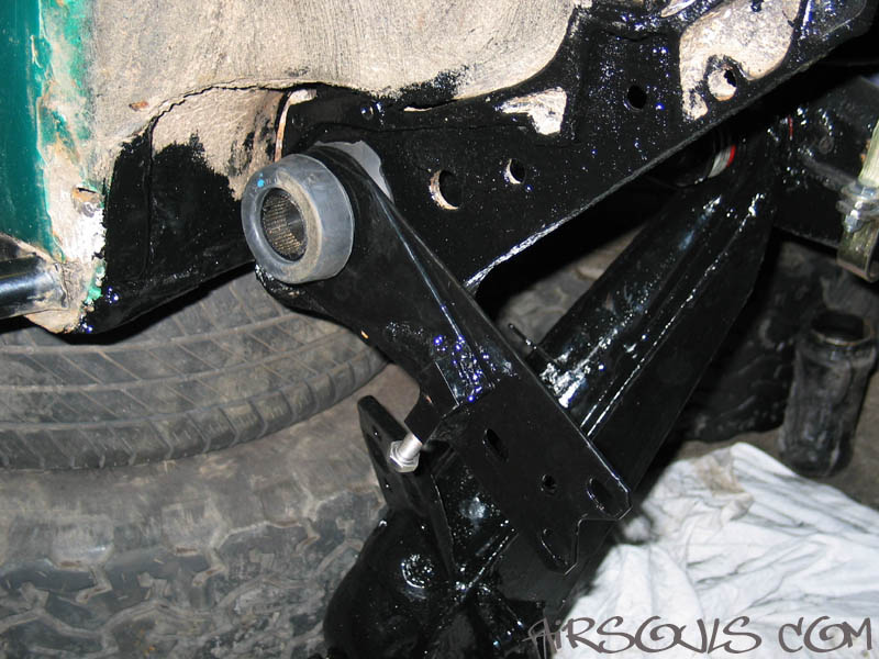
| 10. The new spring plates fit
just like the old ones. New bushings are of course a good idea
when you fit them. The rear (knobbled) bushing will have to
be modified slightly as the new spring plate has a slightly
bigger diameter rear tube. The outer bushing fits on fine though. |
|
|
11. Originally I fitted spacers
behind the torsion bar housing cover, but have since left them
off. There is actually enough space to fit the new plate in
without spacing off the cover. (The swap to allen head bolts
for the cover is just a personal preference.) |
| UPDATES: |
|
|
| U1. I took off my IRS spring
plates to beef them up. I chopped the piece of square bar off
piece A, and then made two strengthening plates from bits of
old spring plates (I have lots!). I made the new piece curved
like the S/A set I made (for strength). After I chamfered all
the edges I welded the strengthening plates on, doubling the
thickness of piece A. |
|
|
U2. Again I welded on something
for the bolt to press against, but didn't need such a thick
bar this time. In the photo you can see that piece A has had
some reshaping. This is because I have notched piece B for longer
suspension travel, and therefore I had to modify piece A too. |
| U3. When I installed the modified
plate I added spacers behind the torsion bar housing cover.
The spacers are just a washer on each bolt placed behind the
cover. I'm very pleased with the modified spring plates and
have confidence in their new strength. |
|
| |
Click an image to view
a larger version. |
|
| That's about it really. My brother
has been using his S/A pair for well over two years now, and
he's still really pleased with them. They work really well,
and he's had no strength problems. The IRS ones I made for
my Baja have been in use for over a year in their first version.
As I said before they weren't stiff enough, so I redesigned
them. So far I'm very pleased with the modified spring plates
and have confidence in their new strength.
Any questions feel free to e-mail. :-)
Log:
Original S/A spring plates fitted: October 2002
IRS spring plates fitted: April 2003
IRS spring plates strengthened: May 2004
|