|
From this...
|
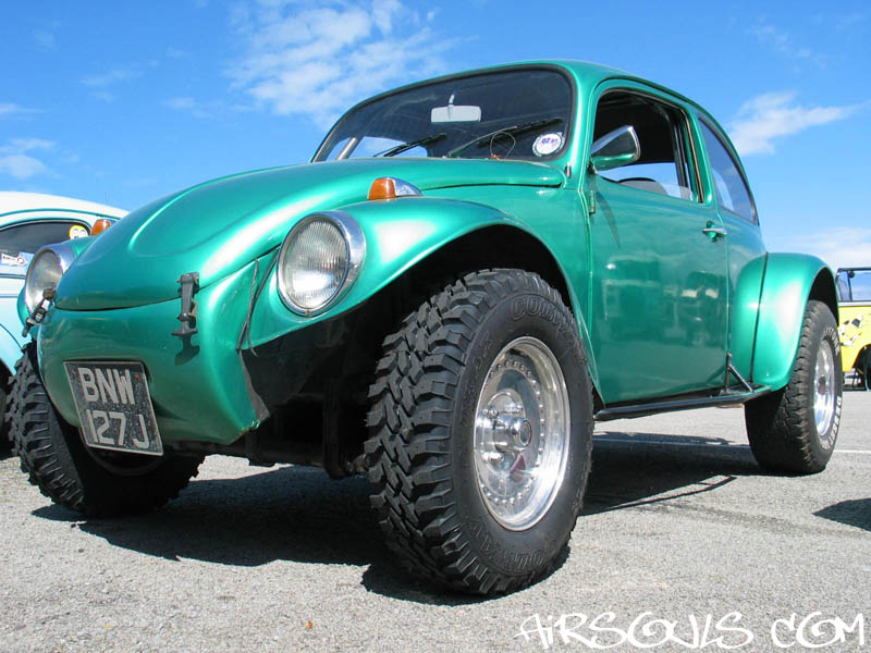
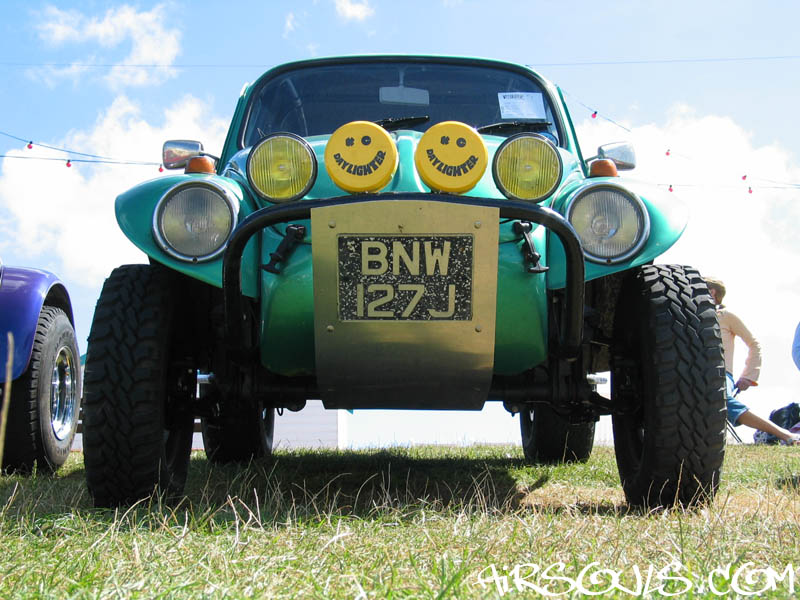
I wanted more ground clearance
and more lift on the front of my Baja so I decided to make
some raised spindles. I had seen some dropped spindles made
by the German Car Company years ago, and it occurred to me
that I could do similar but with a raise. On the left is my
Baja with stock spindles, and on the right with my 2.5"
raised spindles.
You could use this how-to to make dropped spindles, but note
that it does add to the front track (width).
|
...to this.
|
| |
|
|
|
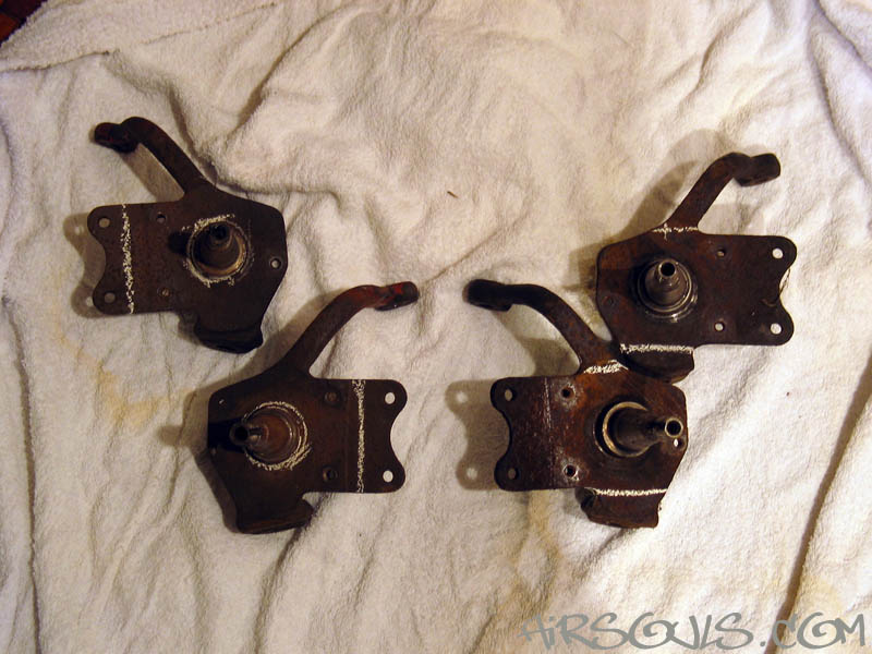
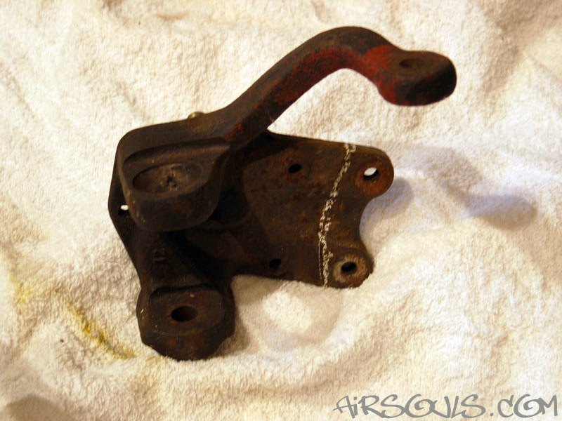
| 1. You need two pairs of
balljoint spindles, which can be drum or disc versions. I
used disc brake ones because they have a greater surface area,
which makes for a stronger join. I also wanted to run disc
brakes on the front. :-D
I picked late disc spindles because the crossover year ones
(1966/67/68) use a smaller inner bearing and track rod end.
Therefore the late spindles (1969 on) are a tiny bit stronger. |
|
| |
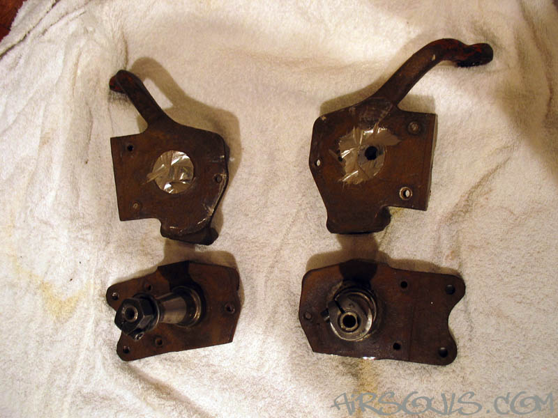
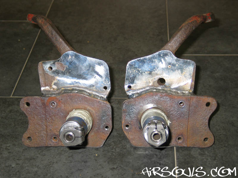
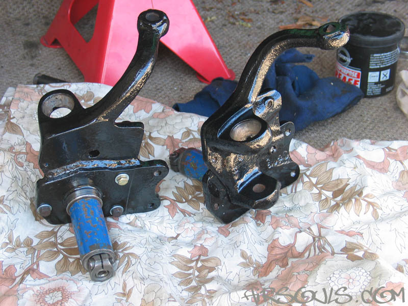
2. On one pair of spindles you
need to chop off the balljoint mounts and the arm that joins
to the trackrod. On the other pair of spindles you need to cut
off the actual spindle part (where the disc/drum joins on) and
the caliper mount.
You can see the cuts you need to make marked in chalk in the
photos on the left. |
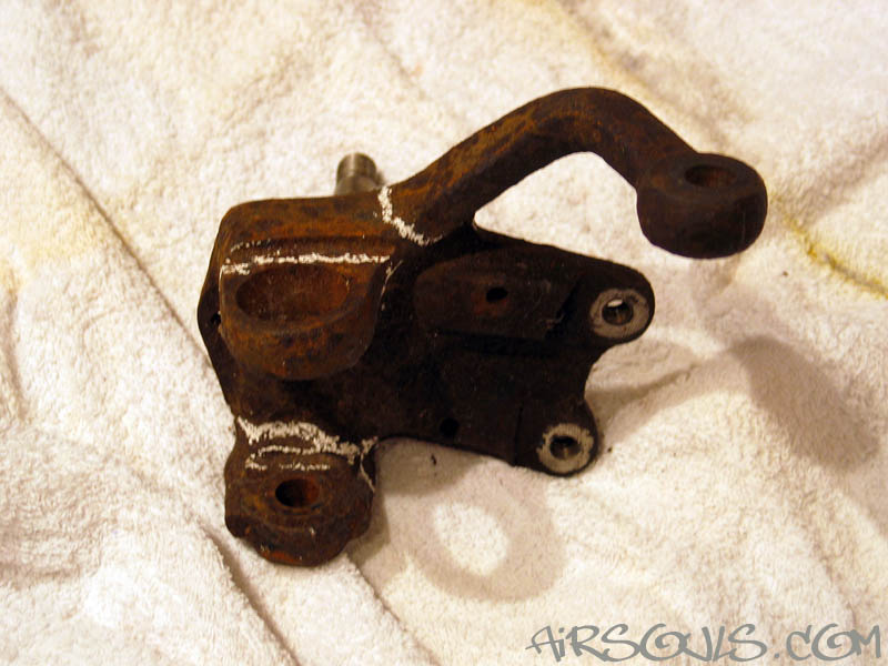
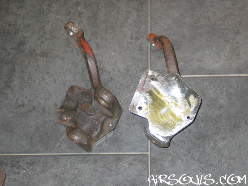
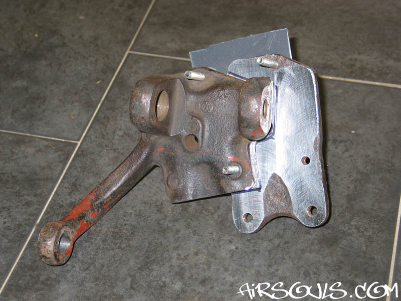
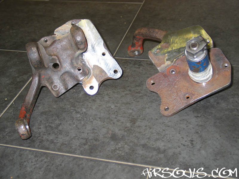
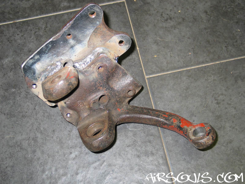
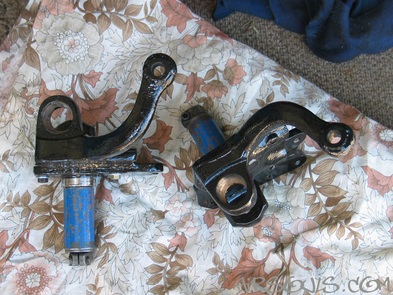
| 3. Here are the
spindles after I have cut them down. Now you can see how the
parts fit together. Make sure you cut the correct spindles,
and don't end up cutting the same bits off both the left spindles!
This is why I marked mine with chalk before cutting them.
|
|
|
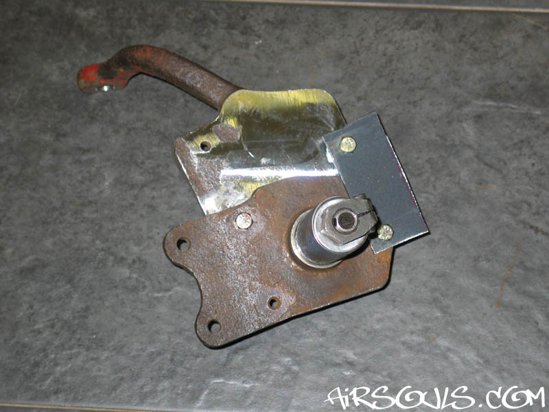
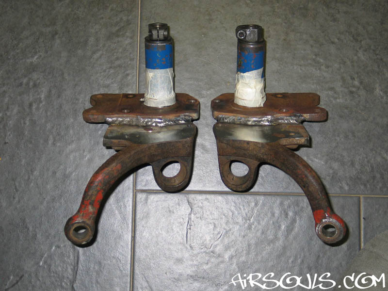
4. To get perfect alignment
I had the mating surfaces machined. The back piece can be
clamped flat using the balljoint mounts. The front piece needs
a short length of tubing (with the ends cut square) slid over
the spindle and clamped in place using the stock washer and
locking nut. Using the tubing this piece can now be clamped
flat.
The thickness of the caliper mount is a good thickness to
machine the front piece down to. |
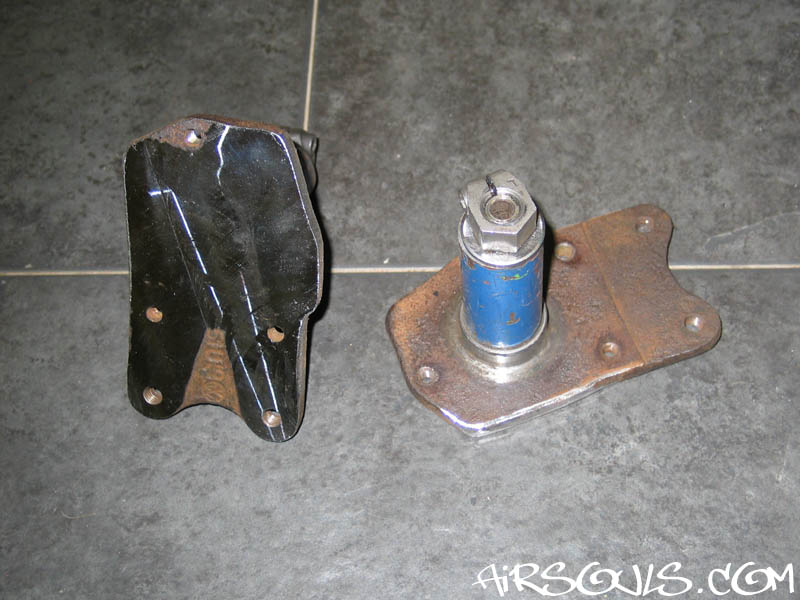
5. Now how do you clamp the
pieces together for welding? This is where the bolt holes
for the backing plates come in handy. If you drill the thread
out of the 'top' mounting hole on the front piece you can
bolt a long 7mm bolt through the front piece into the 'bottom'
mounting hole in the back piece. This gives you a solid mounting
point while you work out how much lift you want.
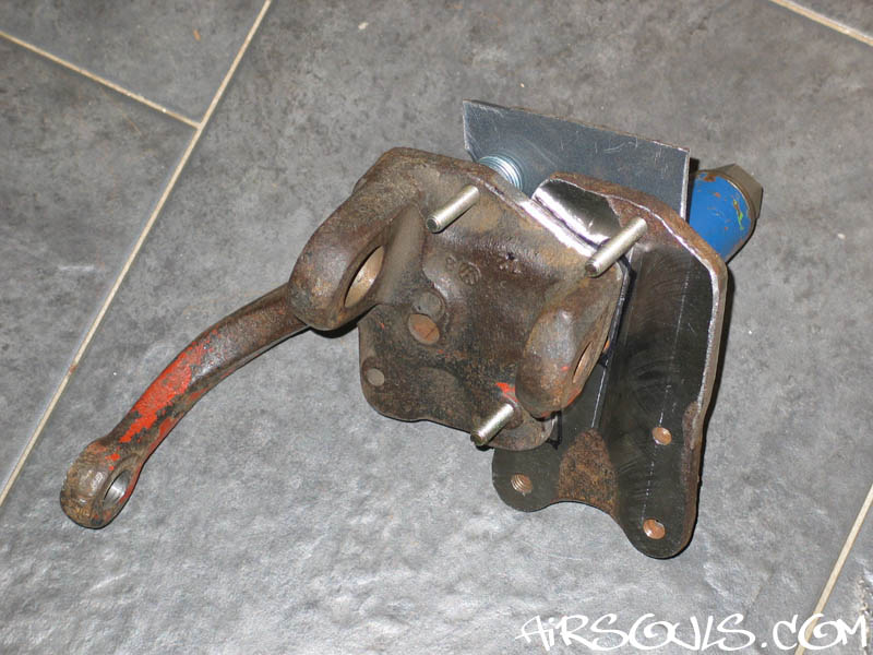
I made two identical plates with identical bolt holes drilled
in to give me exactly 2.5" of raise at the spindle. These
plates bolted to the two 'front' backing plate bolt holes.
Using a few washers as a spacer both spindles were now held
perfectly in position and rock solid. |
|
|
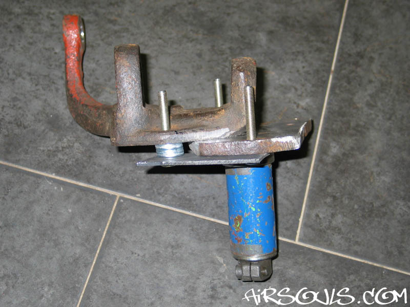
6. Once the spindles were
jigged I marked where they would need to be welded, unbolted
them, and used a grinder on the relevant bits. I then bolted
them together again ready to be welded.
Note: You CANNOT safely weld these together
with your MIG or TIG welder, they need to be professionally
ARC welded.
|
| 7. I took my spindles
to a professional welder and asked how they should be welded,
and if they could do it for me. They said that ARC welding was
the only way to keep the strength needed. My spindles were welded
as a special 'lunch hour' job and only cost me £25. The
guy used their strongest rod, which they normally use on girders,
and said that the weld is good for 4 tons. That's probably more
than the original spindle could take! |
|
|
8. By this stage you've probably
forgotten about the speedo cable! With a 2.5" raise the
hole comes out slightly behind the lower balljoint mount,
and with a little clearancing the speedo cable happy slides
in. I used a speedo cable from a 1303 because they are longer,
but otherwise identical.
Raised suspension + raised spindles = longer speedo cable
needed.
Note: You need to tell whoever does your
welding to leave the speedo cable hole open. |
| 9. Here are the finished spindles,
painted and ready to be fitted. |
|
|
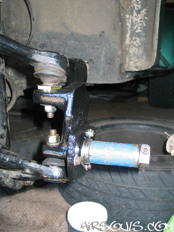
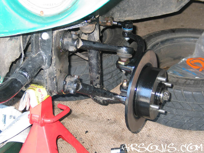
10. Fitting the spindles is identical
to fitting stock spindles. I used the camber adjusting nuts
that you can buy for lowered cars, which offer more adjustment.
After fitting them I discovered that you don't need the extra
adjustment for a raised car, so don't bother. |
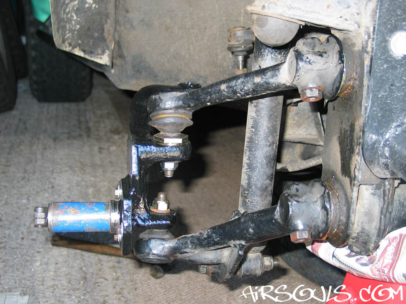
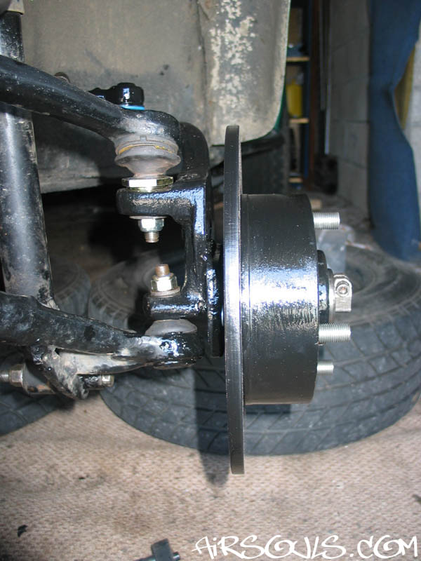
| 11. A couple of photos showing
the spindles on, and then the discs too. |
|
|
12. I decided to run my discs
without backing plates. I made the spindles with the ability
to use backing plates, but after running without on the rear
I decided to do the same on the front. I like being able to
quickly see the condition of the discs with the wheels still
on, and it also makes it easier to wash off mud etc. |
| 13. Once the wheels
are back on the ground set your camber and then tracking as
normal. On the right you can see two photos of my Baja after
I fitted the raised spindles. Much better! |
|
| |
Click
an image to view a larger version. |
|
| I was quite cautious driving
with these raised spindles to start with. A major suspension
component has been cut up and welded back together - failure
of a spindle could cause a nasty accident. This is
why it is VERY important to get the spindles correctly welded
by a professional. After a while I got more confident
in the spindles (I checked them regularly) and drove harder
and harder with them. Now I don't even think about it because
the spindles have happily taken any abuse I have thrown at
them for over a year.
Any questions feel free to e-mail. :-)
Log:
Raised spindles fitted: July 2005
Stripped and checked spindles after a jumping session - still
no sign of cracks etc: September 2007
|